
How I built a barebones WebGL PBR renderer in Nodes.io

This article describes how I implemented a PBR renderer with image based lighting in Nodes.io. The article focuses on structure and the unique challenges faced as well as the advantages of building in Nodes.
This turned out to be a long article so I will drop the source project and playground links right at the top of the page for those who want that most (please be patient with the playground it is large and can take a second to load): Source project // Playground
Introduction
As a hobby project recently I have been building my own renderer, partly to deepen my understanding of WebGL itself but also to have a renderer I understand top to bottom that I can use for personal projects. Physically Based Rendering (PBR) is a rendering equation where real material properties are simulated and simplified to create beautiful results whilst remaining feasible to run in realtime. Because of the elegance and results of this system it has become industry standard for modern realistic rendering so it is what I'll be implementing here.
Nodes is really awesome software where you can create little re-usable blocks of Javascript code inside nodes and connect them up to make your own physical representations of your code structure while running the code in realtime. If you want to know more about it you can visit here to explore the story of its inception.
As I work at Variable, company that makes Nodes, I have been using it for quite a long time. As a result of this, despite the public release being quite recent I have a few years of experience and understand some of the code structures that work well. I think it could be valuable to break down how I'm going about making this renderer, for those interested in learning more about Nodes.
There are many excellent resources where you can learn about realtime rendering techniques, and not many where you can learn about Nodes. Because of that, this article will focus on the latter. This was the first renderer I have ever written from such a low level though so I did use a lot of learning resources myself so I'll link those as I go through.
What this article will cover
- A description and explanation of how I made a WebGL renderer in Nodes.io
- I will list the learning resources I used to learn both the theory and also the code snippets I used as a base.
- How I structured the codebase in a way that meshes well with Nodes
- Any custom techniques I use that are different from the learning resources I post
- Links to source code (as a project file) and a Nodes playground of this graph
- Some downsides of the structure and methods I use.
What this article will not cover
- This is not a 'getting started in Nodes' article, although I hope this will help those who are starting to understand the real potential of Nodes - I will link here a Getting started in Nodes and a Your first graph tutorial for people looking for that kind of content.
- This is not a technical explanation of the maths and science behind physically based rendering - although I will link the learning resources I used.
- This is not tutorial step by step guide of making your own that you can follow along a-z - Although I will provide source code for you to study
- I cannot guarantee that this is the best most efficient way to create a renderer in Nodes - I'm not an industry veteran, this is just the way that made sense to me, despite having flaws.
Overview of tools and libraries
I will be using a few different simple libraries and Nodes to create this, so before I go ahead, lets go over these
- Nodes.io - As described earlier Nodes is a computational thinking tool used to create code snippets that can be structured and linked creating a 2D canvas of your code structure. One of its coolest features is that you can use NPM modules within your nodes and so have access to the full javascript ecosystem - which is why I can use the libraries I list below. You can find out more about nodes at its website Nodes.io
From the NPM ecosystem I will be using the following packages quite extensively throughout the project:
- pex-context - Modern WebGL state wrapper. With
pex-contextyou allocate GPU resources (textures, buffers), setup state pipelines and passes and combine them together into commands. It acts as a low level structure so you don't have to spend a lot of time allocating and binding resources - you just compose your vertex shaders, fragment shaders, attributes and uniforms and some WebGL state variables and off it goes. I did consider writing my own replacement for it in this project but it's battle tested and very flexible so I didn't bother. - pex-math - A very simple functional maths library that deals with vectors, matrices etc as n dimensional javascript arrays. I use this to take the pain out of writing the code to do matrix & vector calculations myself.
- pex-cam - A small module that you can use to create a camera and orbiter object and attach it to your canvas. It handles your projection matrices as well as the mouse interaction and therefore creating and updating your view matrix. This can also save some real pain.
- primitive-geometry - A package exporting geometries for 3D rendering, including normals, UVs and cell indices (faces) as simple arrays.
Learning resources
If you do not already know how realtime rendering works this is when I would recommend you read the following resources. Sadly if you're not familiar with the maths it can seem quite complex, but these are the best resources I have found:
- For WebGL and the basics of rendering you can check out WebGL Fundamentals. This will get you up and running with the basics. Fortunately
pex-contexthandles a lot of what is covered, but knowing the theory is important. - For the majority of the code and theory used in this renderer I adapted from the examples at Learn OpenGL. WebGL is based on OpenGL but they're not identical and not everything is supported in WebGL so it does often need adapting.
Perhaps a better name for this article is 'implementing Learn OpenGL's PBR implementation in Nodes'.
Setting up & structure
As with all code projects its useful to think about the code structure before you start.
The way that I create almost all my real-time Nodes graphs is the same - create some initial state at the top of the Node graph and traverse all the way down the graph every frame. As we send our triggers down the graph we have an object called 'props' that pass down the line and add properties to - nodes downstream can read these and process these properties and keep passing downstream.
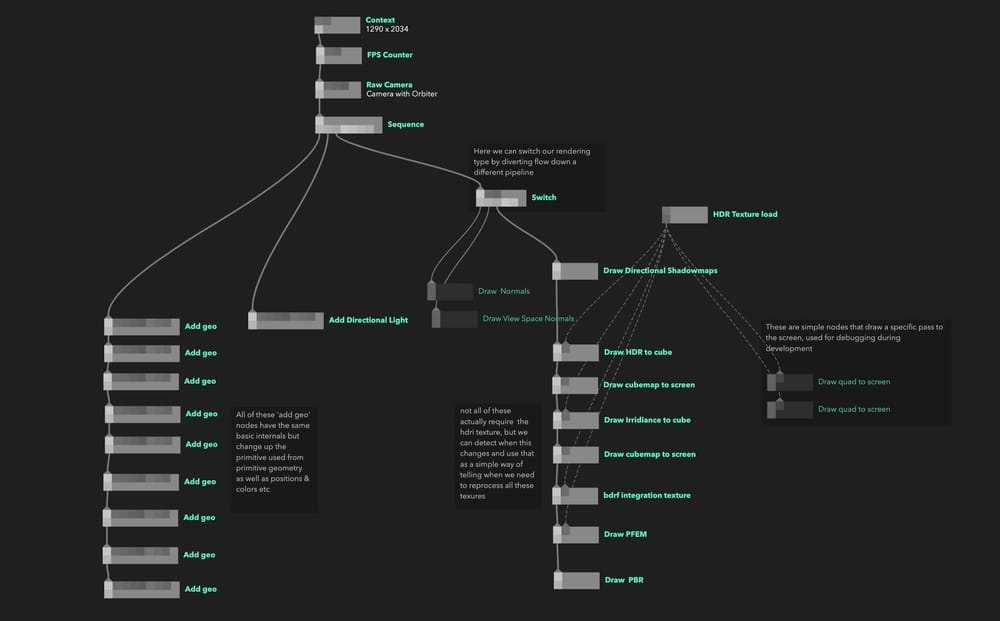
I also knew I wanted to have one node per scene 'entity', so one node representing one mesh or one node being one directional light etc. That leaves us with a graph looks something like this:
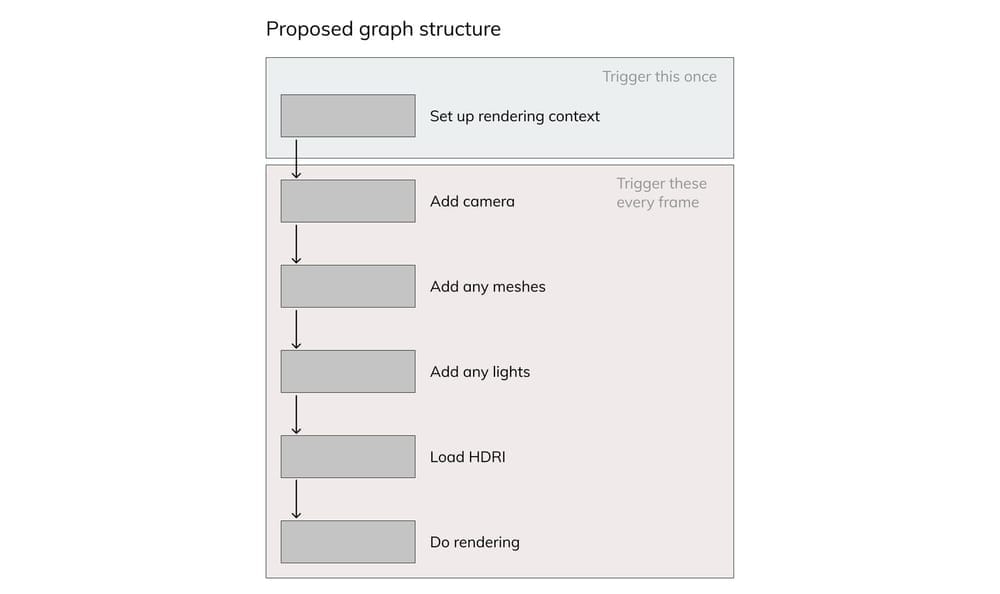
We often end up with these linear structures in our graphs, so we have found a way to organise them. Because triggers between nodes are synchronous we can trigger them in sequentially and the branches of the tree will trigger one at a time. Like this:
module.exports = (node, graph) => {
  const triggerIn = node.triggerIn("in");
  const triggerOut1 = node.triggerOut("out1");
  const triggerOut2 = node.triggerOut("out2");
  const triggerOut3 = node.triggerOut("out3");
  const triggerOut4 = node.triggerOut("out4");
  const triggerOut5 = node.triggerOut("out5");
  const triggerOut6 = node.triggerOut("out6");
  const triggerOut7 = node.triggerOut("out7");

  triggerIn.onTrigger = (props) => {
    triggerOut1.trigger(props);
    triggerOut2.trigger(props);
    triggerOut3.trigger(props);
    triggerOut4.trigger(props);
    triggerOut5.trigger(props);
    triggerOut6.trigger(props);
    triggerOut7.trigger(props);
  };
};
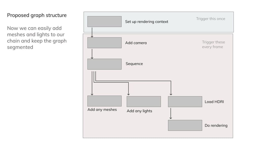
We can use this to segment our codebase so it's easier to visually parse. Our ideal graph now looks something like this:
A benefit here is that one of the free examples provided with Nodes uses a similar structure to this. If we look at at the procedural landscape example it already set up the basics that we need:
- A context node providing our pex-context functionality down the graph, this also handles resizing the canvas for different resolutions
- A camera node that uses pex-cam to attach a perspective camera to the scene and add some orbit controls.
A very simple rendering pass, this one uses matcap for colors so we will remove that but it provides a nice simple base pass to build upon.
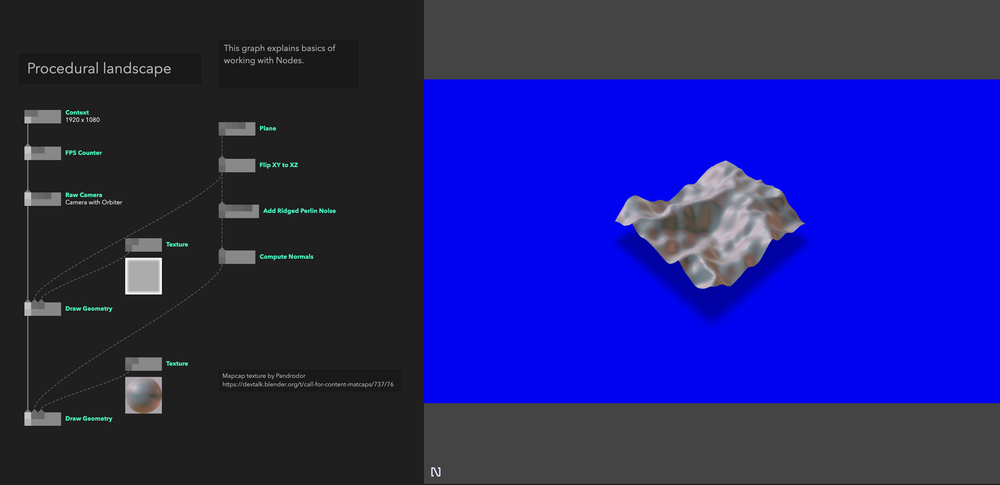
We actually encourage people to use these examples and build on them as starting from scratch can be very daunting, so this is the example that I started with by removing or modifying the nodes as to fit my desire.
Implementation of non PBR nodes
Most nodes that aren't involved in rendering are just creating data structures telling our renderer what it needs, so follow the same basic structure:
- Create the object at the top of the node outside of the trigger callback (and therefore render loop)
- Create parameters for the node that respond to useful properties (mesh transform, material properties, light intensity etc)
- Inside the trigger callback add the object to an array of that type if it exists, if not create that type and add it.
With this general structure we end up with a mesh node that looks like this:
module.exports = (node, graph) => {
  const {
    cube: createCube,
    sphere: createSphere,
    torus: createTorus,
  } = require("primitive-geometry");
  const { mat4, quat } = require("pex-math");
  const triggerIn = node.triggerIn("in");
  const triggerOut = node.triggerOut("out");

  const transformIn = node.in("transform", [0, 0, 0]);
  const rotationIn = node.in("rotation", [0, 0, 0, 0]);
  const scaleIn = node.in("scale", [1, 1, 1]);

  const albedoIn = node.in("albedo", [0, 0, 0, 1], { type: "color" });
  const metallicIn = node.in("metalic", [0, 0, 0, 1], { type: "color" });
  const roughnessIn = node.in("roughness", [0, 0, 0, 1], { type: "color" });

  let meshIn = node.in("mesh", null);

  let meshes;
  let modelMatrix = mat4.create();

  let q = quat.create();
  let geo = createTorus();
  let mesh = {
    geo,
    modelMatrix,
    albedo: albedoIn.value,
    metallic: metallicIn.value,
    roughness: roughnessIn.value,
  };
  triggerIn.onTrigger = (props) => {
    let { ctx } = props;
    meshes = props.meshes || [];

    if (meshIn.value) geo = meshIn.value;

    mat4.fromTranslationRotationScale(
      modelMatrix,
      transformIn.value,
      quat.fromEuler(q, rotationIn.value),
      scaleIn.value
    );
    mesh.geo = geo;
    mesh.modelMatrix = modelMatrix;
    mesh.albedo = albedoIn.value;
    mesh.metallic = metallicIn.value;
    mesh.roughness = roughnessIn.value;
    meshes.push(mesh);

    props.meshes = meshes;
    triggerOut.trigger(props);
  };

  node.onReady = () => {};
  node.onDestroy = () => {};
};
If you are not so familiar with nodes you can notice we require our npm modules at the top of the nodes and they're scoped per node. To use them like this you have to install them from the Nodes > Packages menu.
If you're familiar with the PBR maths it might look strange that the metalness and roughness parameters are colour inputs. This is me planning ahead for when these values will come from textures, I want to make them compatible with rgb colors so I don't have to modify the shader too much later down the line.
In the above code the data we need for rendering is now in the object chain that we pass downstream to the rendering code (as we set props.x = x) . The code to define a directional light could look something like below. Notice how we declare two textures here, a colour and a depth texture and assemble them into a pass. This is used for rendering the shadow map when we get to that step. This version of the renderer only supports image based lighting and directional lights.
module.exports = (node, graph) => {
  const { cube: createCube } = require("primitive-geometry");
  const { mat4, quat, vec3 } = require("pex-math");
  const triggerIn = node.triggerIn("in");
  const triggerOut = node.triggerOut("out");

  const positionIn = node.in("position", [0, 0, 0]);
  const color = node.in("color", [0, 0, 0, 1], { type: "color" });
  const intensity = node.in("intensity", 1, { min: 1, max: 10 });
  const nearIn = node.in("near", 0.01);
  const farIn = node.in("far", 100);
  const widthIn = node.in("width", 10);
  const biasIn = node.in("bias", 0.1);

  let ctx = graph.ctx;
  let shadowMapSize = 512;

  // creates textures and pass for rendering the shadowmap
  let shadowDepthTex = graph.ctx.texture2D({
    width: shadowMapSize,
    height: shadowMapSize,
    pixelFormat: ctx.PixelFormat.Depth,
    encoding: ctx.Encoding.Linear,
    mag: ctx.Filter.Linear,
    min: ctx.Filter.Linear,
  });
  let shadowColorTex = graph.ctx.texture2D({
    width: shadowMapSize,
    height: shadowMapSize,
    pixelFormat: ctx.PixelFormat.RGBA16,
  });
  let pass = ctx.pass({
    color: [shadowColorTex],
    depth: shadowDepthTex,
  });

  // general default light object
  let directionalLights = [];
  let directionalLight = {
    color: [0.1, 0.1, 0.1, 1],
    depthTexture: shadowDepthTex,
    colorTexture: shadowColorTex,
    near: 0.01,
    far: 50,
    width: 10,
    bias: 0.1,
    projectionMatrix: mat4.create(),
    direction: vec3.create(),
    viewMatrix: mat4.create(),
    inverseViewMatrix: mat4.create(),
    pass: pass,
  };

  let viewMatrix = mat4.create();
  let inverseViewMatrix = mat4.create();
  let q = quat.create();

  let ortho = mat4.create();

  let needsUpdate = true;
  function requestUpdate() {
    needsUpdate = true;
  }

  triggerIn.onTrigger = (props) => {
    let { ctx } = props;

    if (needsUpdate) {
      directionalLight.color = color.value;
      directionalLight.intensity = intensity.value;
      directionalLight.near = nearIn.value;
      directionalLight.far = farIn.value;
      directionalLight.width = widthIn.value;
      directionalLight.projectionMatrix = mat4.ortho(
        ortho,
        -widthIn.value,
        widthIn.value,
        -widthIn.value,
        widthIn.value,
        nearIn.value,
        farIn.value
      );
      directionalLight.position = positionIn.value;
      mat4.lookAt(viewMatrix, positionIn.value, [0, 0, 0], [0, 1, 0]);
      directionalLight.viewMatrix = viewMatrix;
      inverseViewMatrix = mat4.copy(viewMatrix);
      mat4.invert(inverseViewMatrix);
      directionalLight.bias = biasIn.value;

      needsUpdate = false;
    }

    if (props.directionalLights) {
      props.directionalLights.push(directionalLight);
    } else {
      props.directionalLights = [directionalLight];
    }
    triggerOut.trigger(props);
  };

  positionIn.onChange = requestUpdate;
  color.onChange = requestUpdate;
  intensity.onChange = requestUpdate;
  nearIn.onChange = requestUpdate;
  farIn.onChange = requestUpdate;
  widthIn.onChange = requestUpdate;

  biasIn.onChange = requestUpdate;

  node.onReady = () => {};
  node.onDestroy = () => {
    ctx.dispose(shadowDepthTex);
    ctx.dispose(shadowColorTex);
    ctx.dispose(pass);
  };
};
You might also note here that on node.onDestroy I dispose of the texture resources. onDestroy is called when a node is recompiled, you change which graph you're viewing in a project or when a node is deleted entirely. It's important to dispose with resources like this or you'll be left with unreferenced resources filling up your memory. Another difference here is that because the maths for calculating the directional directional light properties is quite heavy, we avoid doing it every frame by only rerunning this code when the parameters change using the needsUpdate flag.
Structuring the renderer
For the renderer in its current form we need to do a few render passes; firstly we are supporting directional lights we need to render shadow maps to draw shadows. Then for image based lighting (IBL) we need to pre-render some textures and cube-maps that we can sample during our main render. If you don't know about image based lighting you can read about it on Learn OpenGL here. It is quite complex but I found this to be an excellent explantation, and is the basis for this entire system.
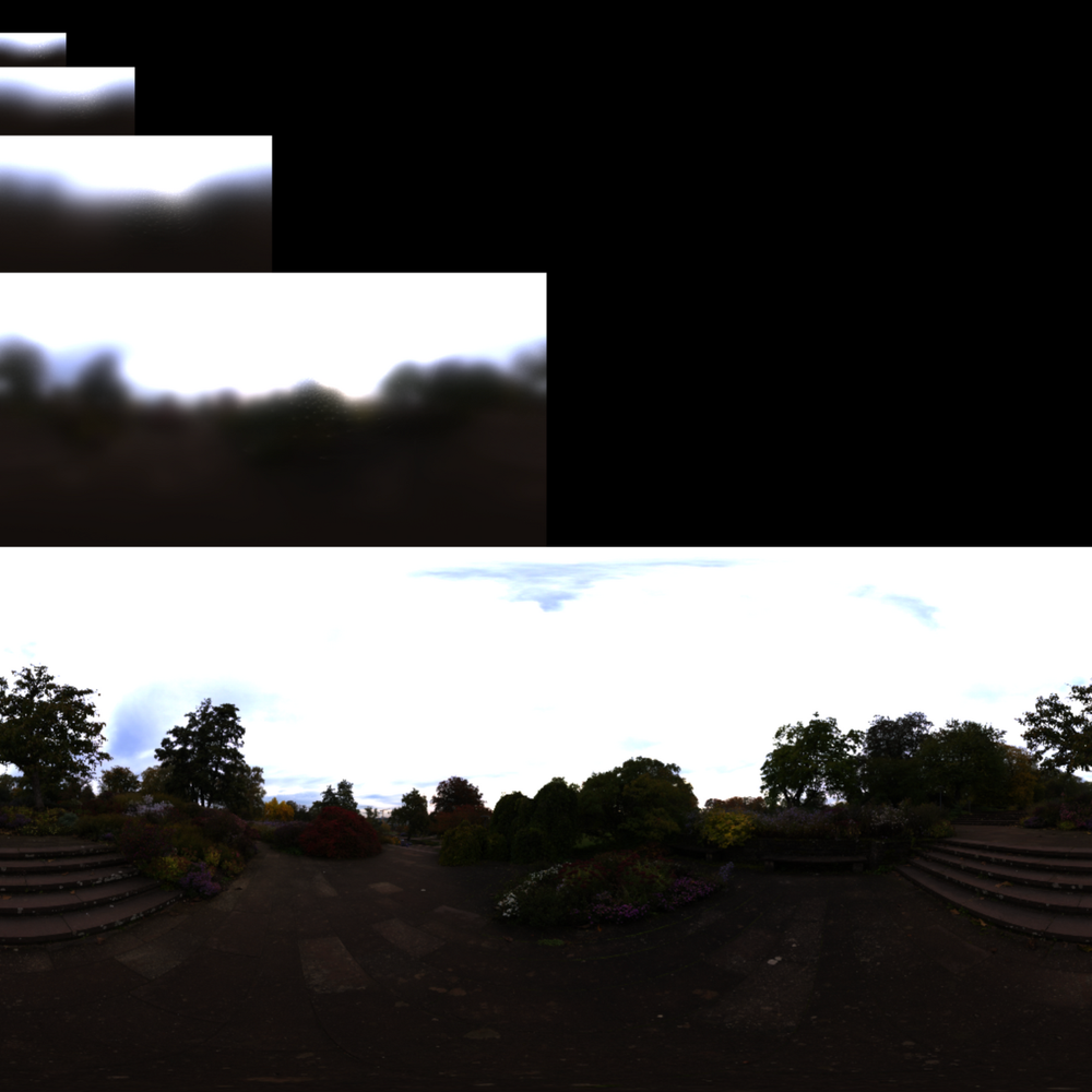
For image based lighting we need to prepare:
- Parse HDRI and draw it to texture
- Use this HDRI to create a cube map
- Create an irradiance cube map
- Create a BRDF Integration texture
- Create pre-filtered environment maps for different material roughnesses
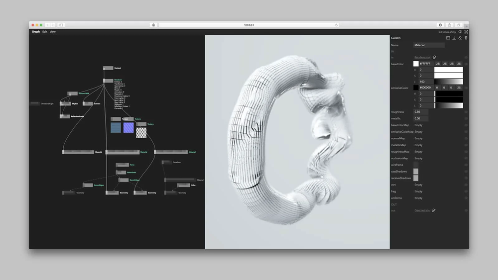
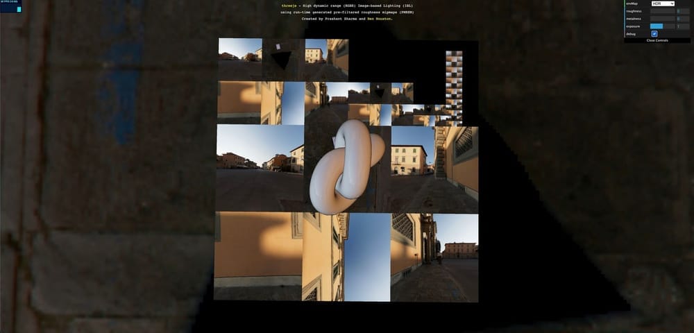
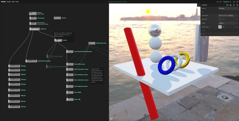
As this the final form of this version of the renderer I can show you what this looks like in practice:
Implementation of shadow map rendering
This shadow mapping code was adapted most from the shadow mapping chapter of Learn OpenGL. In WebGL you cannot only write to the depth texture so I wrote simple shader that works the same way that can be used for debugging. Because I pass the colour and depth texture to the pex-context pass({}) it renders to those textures instead of to the canvas. As these textures are part of the props object already we don't need to re-add them.
module.exports = (node, graph) => {
  const triggerIn = node.triggerIn("in");
  const triggerOut = node.triggerOut("out");
  const enabledIn = node.in("enabled", true, { connectable: false });

  const { vec3 } = require("pex-math");
  const { ctx } = graph;

  let uniforms;
  let vertexNeedsUpdating = false;

  function GetPipeline(aLightNum, dLightNum, pLightNum) {
    let vertString = /*glsl*/ `
      attribute vec3 aPosition;
      attribute vec3 aNormal;
      attribute vec3 aDiffuse;
      attribute vec3 aSpecular;

      varying vec3 vNormal;
      varying vec3 fragPos;

      uniform mat4 uProjectionMatrix;
      uniform mat4 uViewMatrix;
      uniform mat4 uModelMatrix;

        void main () {
        vNormal = aNormal;
        gl_Position =  uProjectionMatrix * uViewMatrix * uModelMatrix * vec4(aPosition, 1.0);
      }
      `;

    let fragString = `
        precision highp float;
        varying vec3 vNormal;
        varying vec3 vPositionView;
        varying vec3 fragPos;
        void main(){
           gl_FragColor = vec4(vec3(gl_FragCoord.z),1.0);
        }
        `;

    return ctx.pipeline({
      vert: vertString,
      frag: fragString,
      depthTest: true,
      depthWrite: true,
      cullFace: ctx.Face.Front,
      blend: false,
      blendSrcRGBFactor: ctx.BlendFactor.SrcColor,
      blendSrcAlphaFactor: ctx.BlendFactor.One,
      blendDstRGBFactor: ctx.BlendFactor.OneMinusSrcColor,
      blendDstAlphaFactor: ctx.BlendFactor.One,
    });
  }

  const drawCmd = {
    pipeline: GetPipeline(),
    attributes: {
      aPosition: ctx.vertexBuffer([]),
      aNormal: ctx.vertexBuffer([]),
      aModelMatrix: ctx.vertexBuffer([]),
    },
    indices: ctx.indexBuffer([]),
  };

  triggerIn.onTrigger = (props) => {
    const { camera, meshes, directionalLights } = props;

    if (enabledIn.value && directionalLights) {
      directionalLights.forEach((light) => {
        ctx.submit(drawCmd, {
          pass: ctx.pass({
            color: [light.colorTexture],
            depth: light.depthTexture,
            clearColor: [0, 0, 0, 1],
            clearDepth: 1,
          }),
        });
      });

      directionalLights.forEach((light) => {
        uniforms = {
          uProjectionMatrix: light.projectionMatrix,
          uViewMatrix: light.viewMatrix,
          uModelMatrix: [],
        };

        meshes.forEach((mesh) => {
          uniforms.uModelMatrix = mesh.modelMatrix;

          ctx.update(drawCmd.attributes.aPosition, {
            data: mesh.geo.positions,
          });
          ctx.update(drawCmd.attributes.aNormal, { data: mesh.geo.normals });
          ctx.update(drawCmd.indices, { data: mesh.geo.cells });

          ctx.submit(drawCmd, {
            uniforms,
            pass: light.pass,
          });
        });
      });
    }

    triggerOut.trigger(props);
  };
};
Rendering the prepared textures for IBL
Loading the HDRI
To load the HDRI i used the npm package parse-hdr and made sure to draw it to a pex-context texture2D with pixel format ctx.PixelFormat.RGBA32F to preserve the high range. You can see the load HDR texture load node handles this. I like to load resources and then pass them to the graph outside of the main render loop as I think it makes the graph a little cleaner
module.exports = (node, graph) => {
  const io = require("pex-io");
  const parseHdr = require("parse-hdr");

  const ctx = graph.ctx;
  const url = node.in("url", "", { type: "asset" });
  const texture = node.out("texture out");

  url.onChange = async () => {
    await processImg();
  };

  async function processImg() {
    texture.setValue(await loadHDR(url.value));
  }
  processImg();

  async function loadHDR(url) {
    if (!url) return;

    const buffer = await io.loadBinary(url);
    const hdrImg = parseHdr(buffer);
    const panorama = ctx.texture2D({
      data: hdrImg.data,
      width: hdrImg.shape[0],
      height: hdrImg.shape[1],
      pixelFormat: ctx.PixelFormat.RGBA32F,
      encoding: ctx.Encoding.Linear,
      flipY: true,
    });

    return panorama;
  }
};
I'm using the Venice sunset HDRI from hdrihaven because I think it gives a lovely soft and warm result.

Drawing the cube map to screen.
Useful for debugging and giving your scene a background, I built a generic node for drawing a cube-map the screen. As its always in the background I draw it first and draw everything else after on top.
module.exports = (node, graph) => {
  const {
    cube: createCube,
    sphere: createSphere,
    torus: createTorus,
  } = require("primitive-geometry");
  const { mat4 } = require("pex-math");
  const triggerIn = node.triggerIn("in");
  const triggerOut = node.triggerOut("out");
  const enabledIn = node.in("enabled", true, { connectable: false });
  const texIn = node.in("texture", null);

  const { vec3 } = require("pex-math");
  const { ctx } = graph;

  let uniforms;
  let vertexNeedsUpdating = false;

  let geo = createCube();
  let mat = mat4.create();

  function GetPipeline(aLightNum, dLightNum, pLightNum) {
    let vertString = /*glsl*/ `
      attribute vec3 aPosition;
      attribute vec3 aNormal;
      attribute vec3 aDiffuse;
      attribute vec3 aSpecular;

      varying vec3 vNormal;
      varying vec3 fragPos;
      varying vec3 vPositionWorld;

      uniform mat4 uProjectionMatrix;
      uniform mat4 uViewMatrix;
      uniform mat4 uModelMatrix;

        void main () {
        vNormal = aNormal;
        vPositionWorld = aPosition;

        mat4 rotView = mat4(mat3(uViewMatrix)); // remove translation from the view matrix
        vec4 clipPos = uProjectionMatrix * rotView * vec4(vPositionWorld, 1.0);

        gl_Position = clipPos.xyww;
      }
      `;

    let fragString = /*glsl*/ `
        precision highp float;
        varying vec3 vNormal;
        varying vec3 vPositionWorld;
        varying vec3 fragPos;
        uniform samplerCube uTex;

        void main(){
            vec3 envColor = textureCube(uTex, vPositionWorld).rgb;
            envColor = pow(envColor, vec3(1.0/2.2));
           gl_FragColor = vec4(envColor,1.0);
        }
        `;

    return ctx.pipeline({
      vert: vertString,
      frag: fragString,
      blend: false,
      depthTest: true,
      depthWrite: true,
      //cullFace: ctx.Face.Front,

      blendSrcRGBFactor: ctx.BlendFactor.SrcColor,
      blendSrcAlphaFactor: ctx.BlendFactor.One,
      blendDstRGBFactor: ctx.BlendFactor.OneMinusSrcColor,
      blendDstAlphaFactor: ctx.BlendFactor.One,
    });
  }

  const drawCmd = {
    pipeline: GetPipeline(),
    attributes: {
      aPosition: ctx.vertexBuffer([]),
      aNormal: ctx.vertexBuffer([]),
      aModelMatrix: ctx.vertexBuffer([]),
    },
    indices: ctx.indexBuffer([]),
  };

  triggerIn.onTrigger = (props) => {
    const { camera, environmentCubemap } = props;

    if (enabledIn.value && environmentCubemap) {
      uniforms = {
        uProjectionMatrix: camera.projectionMatrix,
        uViewMatrix: camera.viewMatrix,
        uModelMatrix: mat,
        uTex: environmentCubemap,
      };

      ctx.update(drawCmd.attributes.aPosition, {
        data: geo.positions,
      });
      ctx.update(drawCmd.attributes.aNormal, { data: geo.normals });
      ctx.update(drawCmd.indices, { data: geo.cells });

      ctx.submit(drawCmd, {
        uniforms,
      });
    }
    triggerOut.trigger(props);
  };
};
Creating an irradiance map
This is a weak link I see in my current implementation. I sample the HDRI multiple times to create an approximation of the irradiance at each pixel of the HDRI. The quality of this depends on the number of samples and needs to be quite high to create nice results. As all this sampling happens in one pass it causes a little stutter as the GPU does the work and draws it to our cube map. Ideally, I would find a way to do this sequentially over multiple frames or find a way to save this irradiance map so it didn't need to be created at runtime when the page is loaded.
Because this is just a cube map like our HDRI cube map, we can draw this to screen with the same node as above, just change the object referenced in props.
The code is getting a bit too long to realistically post here, you can read it in the playground or in the source project though.
Creating a BRDF integration texture
Another part of our IBL is creating a texture that stores the solutions to complex integrations that we can sample during our scene render. The maths is complex but the implementation is simple, creating a texture2D and drawing directly to it, just like all the other data we add it to the props object after it is rendered .
By drawing this texture to the canvas we can get a preview of what this looks like.
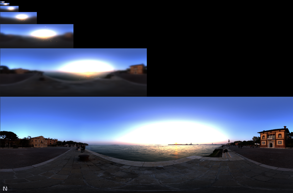
Creating a pre-filtered environment map.
This is the only place I stray far from the Learn OpenGL IBL implementation. The final piece of the IBL puzzle is a pre-filtered environment map, this is similar to an irradiance map except you process it at different roughnesses to be sampled based on material properties. In OpenGL you draw these to a cube map, because the higher the roughness the more blurred the image needs to be you can save memory by drawing the higher roughness values into the mip-maps of the cube map. In WebGL you cant draw directly to your mip-maps so you need to write a different solution.
In Three.js the solution is a very cleverly organised cube map drawn onto a plane at different roughness levels to maximise space, you can see that here.
In pex-renderer they instead use a different system of octahedral maps that fold like origami and pack well because they're square:
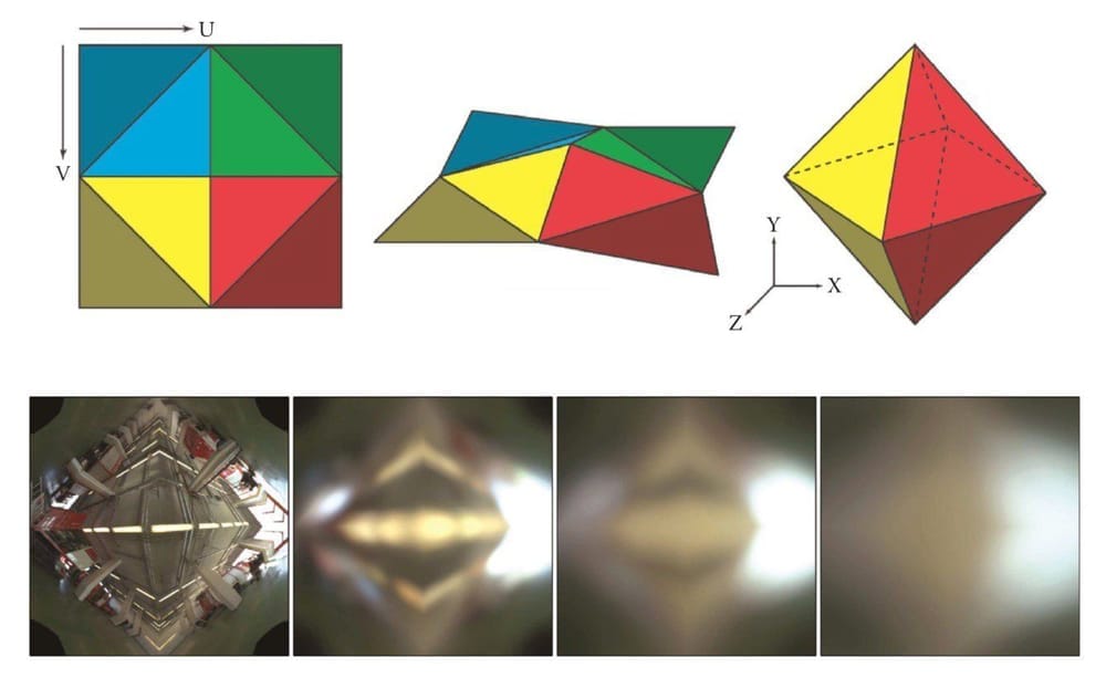
Both of these are awesome solutions, but a little too complex for me to implement just for my hobby renderer.
Instead I decided to pre-filer my environment map and re-save them as equirectangular maps. The benefit here is that it is simple to process and pack, but slower to sample as the spherical - equirectangular conversion is expensive. I'm quite proud of the results however

You can probably notice that there are bright sparks in the texture in the higher roughness levels. This is a common sampling problem and fixing it is still to do. The results are convincing enough for me for now.
Here is the code I used to draw it (trimmed down). Remember you can also explore the full version with the source project or Nodes playground.
module.exports = (node, graph) => {
  const {
    cube: createCube,
    sphere: createSphere,
    torus: createTorus,
  } = require("primitive-geometry");
  const { mat4 } = require("pex-math");
  const triggerIn = node.triggerIn("in");
  const triggerOut = node.triggerOut("out");
  const enabledIn = node.in("enabled", true, { connectable: false });

  const texIn = node.in("texture", null);
  const { vec3 } = require("pex-math");
  const { ctx } = graph;

  let uniforms;
  let vertexNeedsUpdating = false;
  //square in clip space to draw too
  var verts = [
    1.0, 1.0, -1.0, 1.0, -1.0, -1.0, -1.0, -1.0, 1.0, -1.0, 1.0, 1.0,
  ];

  const mipLevels = 5;
  const texSize = 1024;
  const colorTex = ctx.texture2D({
    width: texSize,
    height: texSize,
    pixelFormat: ctx.PixelFormat.RGBA16,
    min: ctx.Filter.Linear,
    mag: ctx.Filter.Linear,
  });

  function GetPipeline(aLightNum, dLightNum, pLightNum) {
    let vertString = /*glsl*/ `
      attribute vec2 aPosition;
      varying vec2 vTexCoords;
      varying vec2 vPosition;
      const vec2 scale = vec2(0.5, 0.5);

        void main () {
            vPosition = aPosition;
            vTexCoords  = aPosition * scale + scale; // scale vertex attribute to [0,1] range
            gl_Position = vec4(aPosition, 0.0, 1.0);
      }
      `;

    let fragString = /*glsl*/ `
        precision highp float;
        varying vec2 vTexCoords;
        varying vec2 vPosition;

        uniform sampler2D uTex;
        uniform float uRoughness;

        const vec2 invAtan = vec2(0.1591, 0.3183);
        const float PI = 3.14159265359;

        vec2 SampleSphericalMap(vec3 v){//sample map;}
        float VanDerCorpus(int n, int base){// do vandercorpus;}
        vec2 Hammersley(int i, int N){// do hammersley}
        vec3 ImportanceSampleGGX(vec2 Xi, vec3 N, float roughness){
            //importance sample based on roughness
        }

        float roughness = uRoughness;
         void main(){
             float lat =  (vTexCoords.x * 2.0 * PI)-PI;
             float lon =  vPosition.y/2.0  * PI;

            vec3 directionVector = normalize(vec3(
              cos(lon)*cos(lat),
              sin(lon),
              cos(lon)*sin(lat)
            ));
            vec3 N = normalize(directionVector);
            vec3 R = N;
            vec3 V = R;
            const int SAMPLE_COUNT = 1024;
            float totalWeight = 0.0;
            vec3 prefilteredColor = vec3(0.0);
            for(int i = 0; i < SAMPLE_COUNT; ++i)
            {
                vec2 Xi = Hammersley(i, SAMPLE_COUNT);
                vec3 H  = ImportanceSampleGGX(Xi, N, roughness);
                vec3 L  = normalize(2.0 * dot(V, H) * H - V);

                float NdotL = max(dot(N, L), 0.0);
                if(NdotL > 0.0)
                {
                    prefilteredColor += texture2D(uTex, SampleSphericalMap(L)).rgb * NdotL;
                    totalWeight      += NdotL;
                }
            }
            prefilteredColor = prefilteredColor / totalWeight;
            gl_FragColor = vec4(prefilteredColor, 1.0);
        }
        `;

    return ctx.pipeline({
      vert: vertString,
      frag: fragString,
      blend: false,
      depthTest: true,
      depthWrite: true,
      //cullFace: ctx.Face.Front,

      blendSrcRGBFactor: ctx.BlendFactor.SrcColor,
      blendSrcAlphaFactor: ctx.BlendFactor.One,
      blendDstRGBFactor: ctx.BlendFactor.OneMinusSrcColor,
      blendDstAlphaFactor: ctx.BlendFactor.One,
    });
  }

  const drawCmd = {
    pipeline: GetPipeline(),
    attributes: {
      aPosition: ctx.vertexBuffer(verts),
    },
    indices: ctx.indexBuffer([
      [0, 1, 2],
      [3, 4, 5],
    ]),
  };

  let needsUpdate = true;

  triggerIn.onTrigger = (props) => {
    const { camera } = props;
    if (enabledIn.value && texIn.value && needsUpdate) {
      let yAccum = 0;
      let rDivisor = 1 / (mipLevels - 1);
      let roughness = 0;
      for (let i = 1; i <= mipLevels; i++) {
        uniforms = {
          uTex: texIn.value,
          uRoughness: roughness,
        };

        ctx.submit(drawCmd, {
          uniforms,
          pass: ctx.pass({
            color: [colorTex],
          }),
          viewport: [
            0,
            yAccum,
            texSize / Math.pow(2, i - 1),
            texSize / Math.pow(2, i),
          ],
        });

        yAccum += texSize / Math.pow(2, i);
        roughness += rDivisor;
      }
    }
    needsUpdate = false;

    props.pfemTex = colorTex;
    props.pfemMipNumber = mipLevels;

    triggerOut.trigger(props);
  };

  texIn.onChange = () => {
    needsUpdate = true;
  };
  node.onDestroy = () => {
    ctx.dispose(colorTex);
  };
};
I know this is a lot to take in, but the key parts here are how we loop for the amount of maps we want to make and each time we pass a different roughness in the uRoughness uniform and use the viewport parameter of the pass to draw in the correct place:
viewport: [0, yAccum, texSize / Math.pow(2, i - 1), texSize / Math.pow(2, i)];
Here are some examples:
Implementation of the rendering equation
I know I'm repeating myself a lot but most of this code is adapted from Learn OpenGL, including this. It's explained well over there! The original source of a lot of the theory and maths is from an explainer released by Brain Karis from Unreal Engine on their implementation of PBR for Unreal Engine 4.
What might interest some wanting to learn Nodes is the implementation of the rendering pass. Because we use structs within GLSL we have to dynamically create our uniforms based on the number of lights in the scene at at the time. We do this by looping through the props object and assigning based on how many there are. As our GLSL code reflects this we have to rebuild our pass if we change the number of lights in the scene and assign the structs based on the number. I built in the functionality here for ambient and point light uniforms as I want to support them one day. It can make the code look quite intimidating but in the shader construction you can see that if there is no point/area lights then no uniforms are passed and no code is added to the shader.
This is far too long to paste here, so have a look in the playground or source and you can cross-reference with the snippets and theory on Learn OpenGL.
I didn't stray from Learn OpenGL's implementation much but I did a little. The first thing I did was gamma correct my colours in the shader instead of using linear textures. I prefer having the color space control all in the same place. I will probably have to change this as a lot of metallic roughness textures assume linear colorspace so shouldn't be converted.
My HDR to LDR conversion for rendering to canvas was also different. In this shader, I opted for an ACES-like transformation as was recommended by Marcin Ignac to really help the colors pop and be vibrant. You can also add a manual exposure value by adding a multiplier at the final step of rendering. I have this hardcoded but it should be a uniform and will be in the next version. Marcin covers some of this theory in a blog post here.
Debugging an ANGLE error
On the original implementation I was encountering an unfamiliar error:
Error: Program: C:\fakepath(283,39-62): error X3004: undeclared identifier 'angle_x' Warning: D3D shader compilation failed with default flags. (ps_5_0) Retrying with skip validation Failed to create D3D Shaders
In Learn OpenGL they put the shadow map sampler2D into Directional Light struct. I don't think this is officially supported in WebGL but the Apple machine I was developing on didn't have a problem with it. On Windows however Chromium converts your GLSL to HLSL for better performance (and because Microsoft get stroppy about GLSL) using angle. This struct conversion was having problems in angle, so I had to change it to passing an array of textures.
Debugging this was the interesting part, first you can check if its a conversion error by forcing your windows machine to render using OpenGL by adding the chrome flag --use-gl=desktop (expect awful performance by the way). If this works as expected you can use a different Chrome flag --enable-privileged-webgl-extension to make it expose the HLSL it writes and then you console log the result. I had to go into my node_modules/pex-context for this project and add code like this:
var vsh = gl.createShader(gl.VERTEX_SHADER);
gl.shaderSource(vsh, shadertxt);
gl.compileShader(vsh);
Easy solution but strange to debug.
Thanks for reading
If you got this far I am very impressed, I know its a huge amount to take in. It took me about a month of the odd evening and weekend to get this all working in its current state. I really hope this showcases the power of Nodes to create explainable and logical code graphs.
One last time the links to the project and playground.
Acknowledgements
Marcin Ignac - Thanks for writing most of the libraries being used here and helping me debug my irradiance. JoeyDeVriez - The creator of Learn OpenGL which I have used extensively and not shut up about during this article.